It is always fun to disassemble something without the burden of reassembling it!
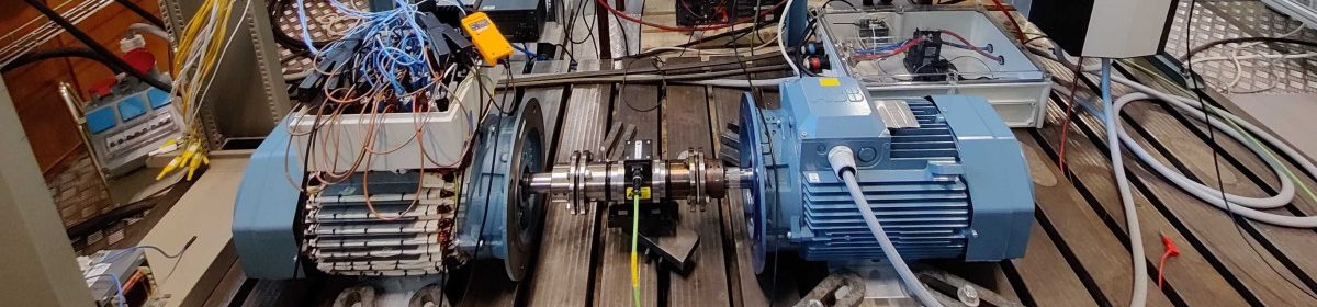
This time an ancient induction machine, MT71B14-4, manufactured by ASEA (The “A” in “ABB”) becomes my victim.
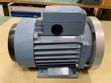
This guy. Let’s do it!
The nameplate says that this machine is rated as class B according to the IEC standard 34-1-1960. Its rated power is 0.37 kW, rated rotating speed is 1400 rpm, and rated power factor is 0.69. If the “Y-connection” is adopted for the three phase of stator windings, its rated linear voltage is 380 V and rated current is 1.3 A; while if the “Delta-connection” is adopted for the three phase of stator windings, its rated linear voltage is 220V and rated current is 2.3 A.
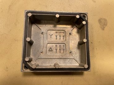
The connection methods of electrical cables for them are illustrated on the backside of its lid.

Obviously the “Y-connection” is adopted for the three phase of stator windings.
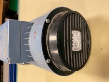
The non-drive end has a centrifugal fan which helps cool the machine with forced air convection.
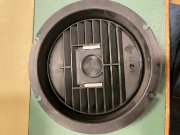
The cover with louvers.

The cowling which guides the airflow into open channels between fins on the casing.
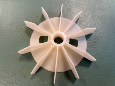
The fan has radial straight shape blades, which makes it able to work in both rotating directions.
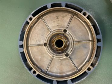
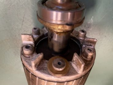
The endcap, which fixes the position of the bearing and support it.
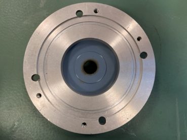
The flange in the drive end, guessed to be used for connecting with the load machine.
There are 24 slots in total for the stator.
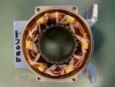
Random windings are used for this kind of small size squirrel caged motor.
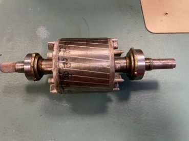
Rotor bars are skewed to improve the starting torque, prevent the magnetic locking between the rotor and the stator.
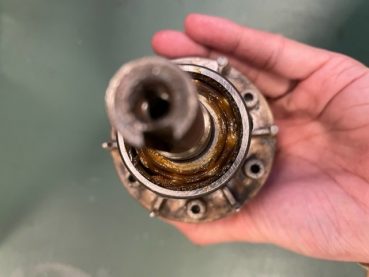
A common ball bearing is used in this machine.
There are two washers below a specific bolt at the end ring to balance the weight of the rotor.
Where are my chainsaws? Now I will cut these endwindings off…
P.S. Thanks to Jesper Freiberg for the help in the disassembling process.