Electric machines die; did you know that? And if you feed them pulse-width-modulated voltages, they will die younger.
This is a well-established fact in the electrical machine community: switching voltages at the terminals of an electric machine, especially when the switching has a very steep rise/fall time, is a serious issue for the bearings and the winding insulation. Failure statistics show that bearings are the #1 failure in electric drive systems, followed by winding insulation failures at #2.
It’s hard to estimate when your electrical machines will actually fail. And you don’t want it to happen unexpectedly in your industrial process, robot, or electric ambulance. It will leave you in dire straits with potentially high losses (of money or even human lives).
There is significant scientific activity on electric machine lifetime estimation. Here at KTH, we chose to work on winding insulation failures, because of the potential expansion of SiC and GaN power electronic devices in drives – which pose a serious issue to the insulation due to their very high dv/dt during switching.
Rather than artificially inducing faults, we decided to accelerate the ageing of a standard industrial motor and progressively monitor different variables throughout the process. It is a difficult task that requires careful hardware and software preparation, but it was worth the attempt.
How to evaluate the winding insulation degradation?
Among the different possibilities, we looked into methods that monitor degradation by indirectly tracking changes in the parasitic capacitances of the stator windings. Those parasitic capacitances are related to the dielectric properties of the insulation, and thus they change when the insulation is degrading. In practice, the parasitic capacitances become smaller as the motor is aging, due to the formation of unwanted air bubbles in the insulation material (and thus, inducing weaker dielectric properties).
How to monitor the parasitic capacitances, then?
In principle, you can measure them with special equipment when the machine is still. However, we don’t want to do that: we want the machine to continue operating while we monitor its insulation state. And here is the fun part: the pulse-width-modulated voltages from the frequency converters are actually exciting the parasitic capacitances. You can notice that by zooming in with an oscilloscope when a switching device goes on or off:
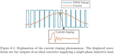
Here are some real measurements as examples:
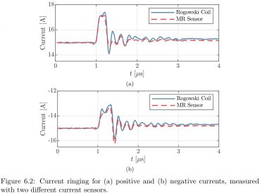
Those oscillations, which go on for very few microseconds, are not noise. It is the resonance effect between the inductances in the machine and the parasitic capacitances, caused by the quasi-square-wave voltage applied at the machine terminals.
So, in principle, if you monitor those oscillations and record changes in shape/amplitude over time, you have insulation degradation monitoring. Easier said than done.
The problem is that those oscillations are very difficult to catch (we are talking about at least 5 MHz of spectral range). In addition, the rules on how they change over time as a function of the insulation degradation state are basically unknown, and they are temperature-dependent.
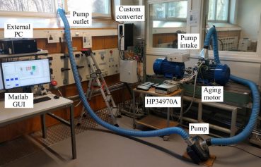
Since we are a bunch of destroyers, we tried to look into one case anyway. Our bench is shown below. The machine under test was aged in an accelerated fashion by overloading it while recording the high-frequency oscillations to find the descending trend of parasitic capacitances. It took approximately six weeks of continuous overloading to kill the machine while sucking out of the laboratory all the fumes coming from melted materials.
Are you interested in the results? Look at the doctoral thesis of our Knight Giovanni Zanuso.