Pin-planning in Quartus (en)
 Pin-planning in Quartus

The lab code locks has different wiring. MAX chips must therefore be programmed differently to fit the equipment.
Quartus has a Pin-planning function. Either you can let the compiler choose pins for the various signals - And then adapt the wiring after this, or the wiring is determined in advance (which is the case here) and then you have to self pair signals with pins.
![]()
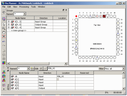
Start Pin Planner. Menu Assignements, choose Pin Planner, or by clicking on the icon for Pin Planner.
You write the pin-number you want to assign in the column Location. Double click in the box to get a list of possible pins. In the column Fitter Location shows which pin the autofitter function has selected - but it is usually possible to make other choices yourself.

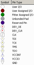
In the pinnplanner there is a picture of the pin layout for the selected chip, and a list of the variables/signals that has occurred in the VHDL code.
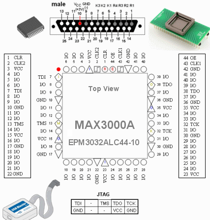
MAX3000-chip has 44-pin. Some of them are occupied for supply voltages. Often MAX circuits are used to connect digital equipment using different supply voltages, but since we do not have such needs, we have linked all those pins to the same supply voltage + 3V.
Other pins are used for chip programming, they are connected to the so-called JTAG connector (TDI TMS TCK TDO).
There are two clock inputs, one enable input and one reset input. Pin that are not used can be left unattended because the compiler makes sure they are disconnected.
Total remaines 26 user defined pins, to freely use as inputs or outputs.

Connections to the lab breadboard
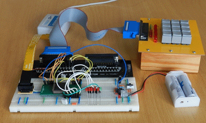
The keys on the keyboard are arranged as a matrix with four rows and three columns as a total of seven lines, connected to a DB-25 connector. The output signal is one yellow LED, and five red LEDs used to present the code lock internal state

MAX-chip is contained in a TQFP-44 package. To use the MAX circuit on a breadboard, we have acquired an adapter, a breakout-board, which has pins positioned as a DIL-44 chip.
The figure shows the pin placement on the MAX-chip and on the breadboard.
MAX-chip has many voltage connections. You can take them to help orient you on the breadboard.
(3 VCC, 10 GND, 15 VCC, 17 GND, 22 GND, 42 GND, 36 GND, 35 VCC, 30 GND, 23 VCC.)
Labassistants has access to facit-files for the different lab equipment versions.
With them, we can quickly rule out possible problems, eg. if you have entered the pin numbers incorrectly.