Visa version
Visa
< föregående
|
nästa >
Jämför
< föregående
|
nästa >
Lab1 wiki (en)

Chips and Breadboard

At the labs, we use digital circuits from the so-called 74-series of capsules of the DIL type (Dual In Line) for hole PCB assembly. See the picture. This is today considered to be pure spare parts, and development has changed to completely different package types for surface mounting.
These old circuits, are however unbeatable for experiments with simple connections on the breadboard. Breadboard are now also used with very complex circuits - then mounted on Breakout Board (a breakout board has the same pin spacing DIL) circuits. Working with circuits on the breadboard is therefore the natural working method for project work and theses for school and hobby activities.
Fritzing Is the name of a software for documenting breadboard connections, and generate circuit diagrams, and possibly manufacture printed circuit boards. (This program will be used in the course IE1206 but is not needed for this course). Anyone interested can download it now.
Data sheets for laboration circuits
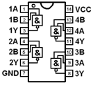
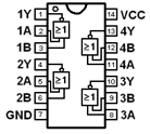
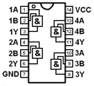
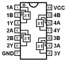
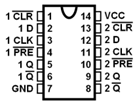
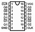
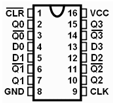
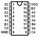
The digital components have capsules with 14 or 16 pins. For orienting the capsules they have an outlet on the short side, and there can also be a "dot" to mark the pin number 1. Two of the pins should be connected to the supply voltage and ground and the other pins are used as logic inputs and outputs, sometimes a pin can lack connection to the inside of the chip, it is then called NC (no Connection). The pin function is stated in the data sheets, and to some extent also in the symbols in the figures.
Some warnings.
Two outputs may not be connected with each other. It will be a so-called short-circuit and the output value becomes uncertain 1/0 (?). Unconnected inputs picks up electrical interference and must therefore also be considered unsafe 1/0 (?). They should therefore always be connected to an appropriate fixed level 1/0 depending on the function.
Breadboard
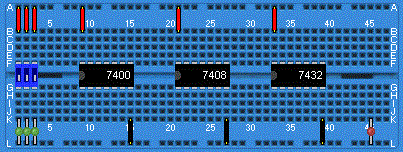
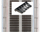
Breadboard at the lab. Supply voltage and ground are already connected to circuitry on the labequipment. To the right is a picture of the coupling underside of the deck with the contact springs visible, and a picture of a contact spring for five holes.
Breadboard at the lab. The chips are inserted in the holes on the plastic isolated side. On the underside there are contact springs of metal that electrically connects to the pins and for further connection to four additional holes. Connector cables can then be entered in the holes to pass on the connection to other pins.
The contact springs are in groups of five holes vertically. This corresponds to a connection point (a node) in a wiring diagram. In the middle of the breadboard is an insulating "ditch" so that the pins on the chips both long sides are isolated from each other. Coupling on long sides of the board have extra long contact springs, so that all the holes are here connected to each other. The long side holes are used to connect the supply voltage and ground to the other circuits. Upper long side holes are all connected to + 5V and lower long side to ground (0V).
Many breadboard has double rows of holes on the long sides - each side of the board can then have both the supply voltage and ground. Then you can avoid having to draw cables over the chips, this facilitates in the case that one chip fails and must be replaced.
Long breadboards often has long side contact springs divided into two sections and two rows. The sections can then be used for several different supply voltages to the circuits - no standard for this does exist - for such a case, you simply carefully has to find out what applies!
Other components
