VHDL for a codelock (en)
 VHDL for a codelock
Description of the codelock template
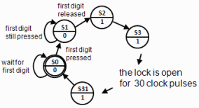
The Code Lock template applies to a simplified lock that opens when you press the key "1" and then release the key.
Almost all digital designs are now carried out using high-level languages like VHDL/Verilog. Our basic course in digital technology does not allow to teach VHDL language, however, you will be able to transform the "template code lock" into useful VHDL code at the lab.
If you think that the VHDL language seems interesting, then the school has several advanced digital technology courses
lockmall.vhd
library IEEE;
use IEEE.std_logic_1164.all;
use IEEE.std_logic_arith.all;

entity codelock is
   port( clk:      in  std_logic;
           K:      in  std_logic_vector(1 to 3);
           R:      in  std_logic_vector(1 to 4);
           q:      out std_logic_vector(4 downto 0);
           UNLOCK: out std_logic );
end codelock;

architecture behavior of codelock is
subtype state_type is integer range 0 to 31;
signal state, nextstate: state_type;

begin
nextstate_decoder: -- next state decoding part
process(state, K, R)
 begin
   case state is
      when 0 => if (K = "001" and R ="0001")     then nextstate <= 1;
                else nextstate <= 0;
                end if;
      when 1 => if (K = "001" and R = "0001")    then nextstate <= 1;
                elsif (K = "000" and R = "0000") then nextstate <= 2;
                else nextstate <= 0;
                end if;
      when 2 to 30 => nextstate <= state + 1;
      when 31 => nextstate <= 0;
   end case;
end process;

debug_output:  -- display the state
q <= conv_std_logic_vector(state,5);

output_decoder: -- output decoder part
process(state)
begin
  case state is
     when 0 to 1  => UNLOCK <= '0';
     when 2 to 31 => UNLOCK <= '1';
  end case;
end process;

state_register: -- the state register part (the flipflops)
process(clk)
begin
  if rising_edge(clk) then
     state <= nextstate;
  end if;
end process;
end behavior;
Moore machine
The code lock is The code lock is designed as a Moore machine.
The different blocks in the code are identified with "labels".

VHDL processes
With a "process" you can describe what should be performed in a block without having to go into the details of how this should be done.
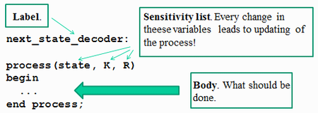
VHDL code is written as such processes.
Parts of the program
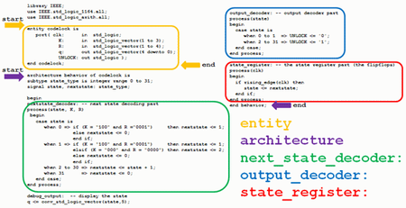
entity architecture next_state_decoder: output_decoder: state_registers:
entity
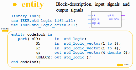
Programmets entity är en beskrivning av kodlåset som en "black box" med insignaler och utsignaler.
Bits and Bitvectors
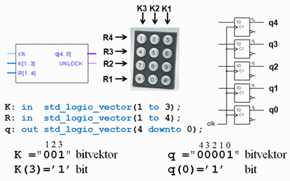
You can customize the indexing of variables so that it is consistent with the data sheets - less risk of mistakes!
Architecture - define suitable datatypes
Avsnittet architecture innehåller beskrivningen av blockets beteende.
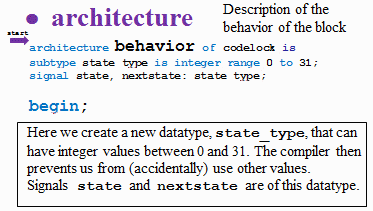
Here we create a new datatype, state_type, that can have integer values between 0 and 31. The compiler then prevents us from (accidentally) use other values. Signals state and nextstate are of this datatype.
Architecture - next state decoder
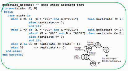
Next statre decoder is the central part of the program. By using the case-statement you can write the code in such a way that it confirms to the state diagram.
Troubleshooting help - the state is shown with five LEDs

To troubleshoot, we want to be able to follow which state the machine is in. The function conv_std_logic_vector() converts ,state (an integer between 0...31) to to a 5-bit bitvector q, q(4) ... q(0). In order to use this conversion function one has to include the library IEEE.std_logic_arith.all.
Output decoder
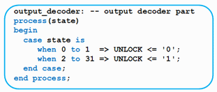
The output decoder is written "straightforward" by a case-statement.
State register

By using the function rising_edge(clk) we let the compiler "understand" that we want to use the flip-flops inside the MAX-chip in order to build a register.
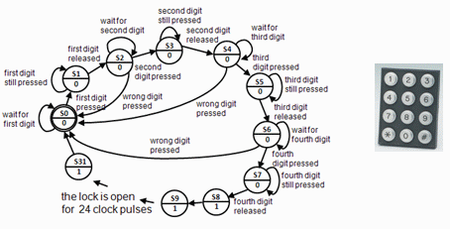
At lab you expand this code to create a four digit code lock!
